Measurements and network audit
-
Measuring instruments
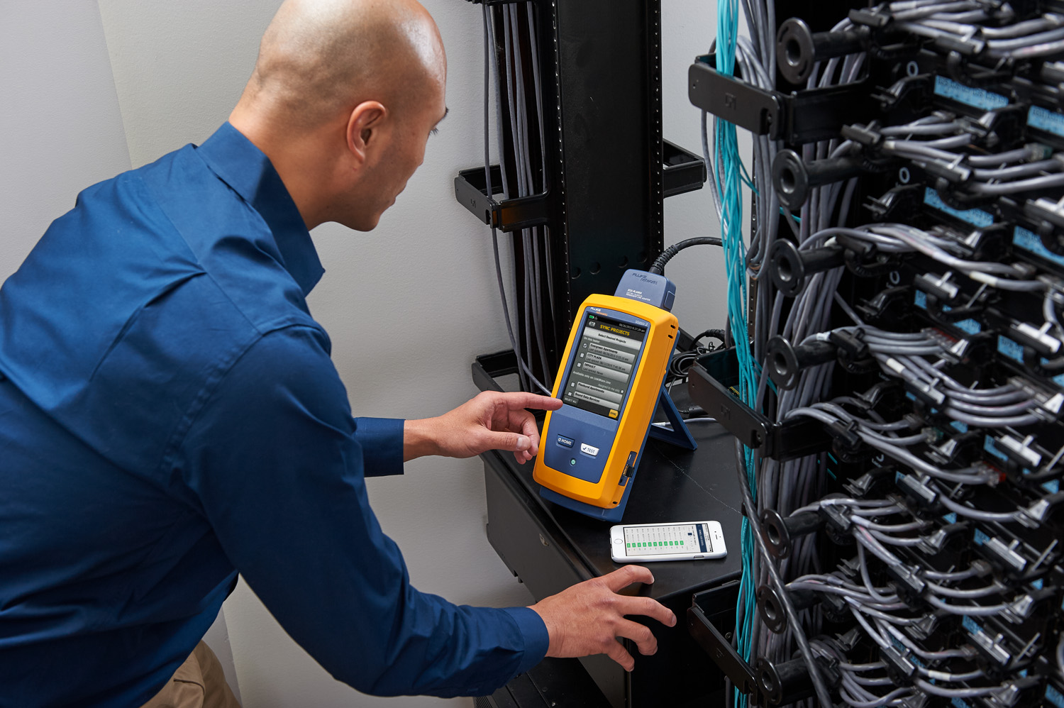
- DSX-5000 from Fluke Networks with adapters from the CertiFiber Pro series.
- OptiFiber Pro Quad reflectometer.
-
Measuring standards
Category 3, 4, 5, 5e, 6, 6A, 8 according to ANSI/TIA-568.2-D
Class C, D, E, EA, F, FA, and I/II according to ISO 11801 and EN 50173
Certification of patch cords category 5e, 6, 6A, and M12 according to ISO and EN
Inspection of optical connectors according to IEC 61300-3-35 ED.2
Tier 1 and Tier 2 certification in accordance with ISO 11801, ISO 14763-3, TIA 568.3-D
Purpose of measurements
All measurements are designed to check the structural cabling against common norms and standards. Structured cabling systems are described by international standards and norms that define their parameters. The measurement performed by the structural cabling testers is intended to relate their results to the limit values determined by the defined norms and standards. Measurement results are the basis for further certification of structural cabling. The correctness of the tests enables verification of the cabling (cable structure of the computer network) in terms of transmission capability. Tests performed with the use of the above mentioned testers are the answer to the basic questions, which refer to the transmission capability of cables. Tests unequivocally check whether our computer network meets the requirements (parameters) set for the transmission channel type 10GBase-T, 5GBase-T, 2.5GBase-T, 1000Base-T, 100Base-TX czy tylko 10Base-T. They also verify the ability of the tested tracks to transmit PoE power in accordance with IEEE 802.3 bt guidelines.
Ask for an offer
Tested parameters
I. Copper wiring
When testing cabling, we measure physical parameters of transmission paths, which can be divided into three categories:
-
1. Mechanical parameters
a) correct connection of wires (connection map) - checking correctness of wire connection
b) length of transmission paths (length of wires l [m])
2. Propagation parameters
a) propagation delay (tp [ns])
b) delay error (Dtp [ns])
c) attenuation (ATTN [dB]) - is a parameter determining signal loss in the transmission path
d) characteristic impedance (Zo [ohm]) - is a parameter closely related to cable geometry (wire thickness, distance between wires) and represents a measure of heterogeneity, track deformations
e) reflection loss (RL [dB]) - are measures to take account of impedance mismatch and track heterogeneity
-
3. Parameters related to electromagnetic compatibility, these are mainly parameters describing the phenomenon of crosstalk
a) NEXT - Near-End Crosstalk [dB] - similar crosstalk describing the value of crosstalk from a given track, measured from the proximal end of the transmission track
b) FEXT - Far-End Crosstalk [dB] - remote crosstalk, describing the crosstalk value from a given track, measured from the distal end of the transmission track
c) PS NEXT - Power Sum Near-End Crosstalk [dB] - crosstalk coefficient, describing the value of NEXT crosstalk from many adjacent tracks
d) PS FEXT - Power Sum Far-End Crosstalk [dB] - crosstalk coefficient, describing the value of FEXT crosstalk from many adjacent tracks
e) EL FEXT - Equal Level Far-End Crosstalk [dB] - crosstalk coefficient, describing the value of crosstalk from a given NEXT track with the difference that the measurement is from the opposite end in relation to the signal generator
f) PS ELFEXT - Power Sum Equal Level Far-End Crosstalk [dB] - crosstalk coefficient, the idea is similar to the parameter EL FEXT, with the difference that crosstalk comes from many neighboring tracks
g) concurrent interference loss (LCL [dB]) - measure of track balance, the coefficient describes the measure of signal distortion introduced by the track
II. Fiber optic cabling
-
1. Basic (certification, Tier1) tests - performed with the CertiFiber Pro Quad series tester enabling certification of multi-mode and single-mode cabling
a) attenuation [dB]
b) length [m]
c) propagation delay [ns]
d) continuity
-
2. Extended tests (reflectometric, Tier2) - performed using an OptiFiber Pro Quad series reflectometer.
a) Insertion loss / insertion loss or permanent link
b) propagation delay
c) length of channel or permanent link
d) optical fiber attenuation / insertion loss
e) reflective losses of connecting hardware
f) continuity


