Fiber Optics - Today and Tomorrow's Technology
To Fiber Optic Instalation Cables >
To the full range of Fiber Optic Networks >
Basics - Terminology, Construction
-
Fiber optic cabling is currently the primary transmission medium in data networks (including LANs) where high network performance is required, and data transmission over distances exceeding 100 meters is necessary (100 meters is the data link length limit for copper cabling). Fiber optic cable, the fundamental component of every fiber optic cable, is constructed from quartz glass, which is comparable in thickness to a human hair. This fiber enables data transmission through light waves. The path that the light beam (photon beam) follows is called the mode. If only one mode of transmission is possible in a given fiber, i.e., a single mode, then we are dealing with single-mode fiber. However, if the light beam can travel through different paths, i.e., different modes, then it is a multi-mode fiber.
-
Therefore, depending on the type of glass fiber used in a specific fiber optic cable, fiber optic cabling can be divided into two primary groups:
- Single-mode cables, denoted by manufacturers as: SM, 9/125, OS1, OS2
- Multi-mode cables, denoted by manufacturers as: MM, OM1, 62,5/125 – only for OM1, OM2, OM3, OM4, OM5, 50/125
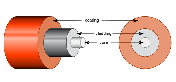
Figure 1: Construction of an optical fiber
-
Numerical designations used to describe optical fibers such as 9/125, 50/125, and 62.5/125 are based on the geometric dimensions of the optical fibers. An optical fiber consists of two layers: the inner layer, called the core, which has a diameter of 9µm (single-mode fibers) or 50µm or 62.5µm (multimode fibers), and the outer layer, known as the cladding, with a diameter of 125µm.
To enable the propagation (spread) of light photons within the core of the optical fiber (NOTE: light only travels inside the core), the glass layer used in the cladding is doped with elements such as titanium, germanium, or boron. Glass optical fibers, which are very delicate and fragile in their structure, are protected from external conditions by a protective buffer, which is a layer of colored acrylic applied to the fiber. This layer adds to the overall diameter of the fiber, making it either 250µm (referred to as "loose-tube" construction) or 900µm (referred to as "tight-tube" construction).
It's worth noting that the colored buffer layer on the fibers is used to identify the order of the fibers during splicing (i.e., fiber connections), allowing for efficient fiber management during installation work. An example of how the color-coding of optical fibers is organized within a specific tube is shown next to this description. -
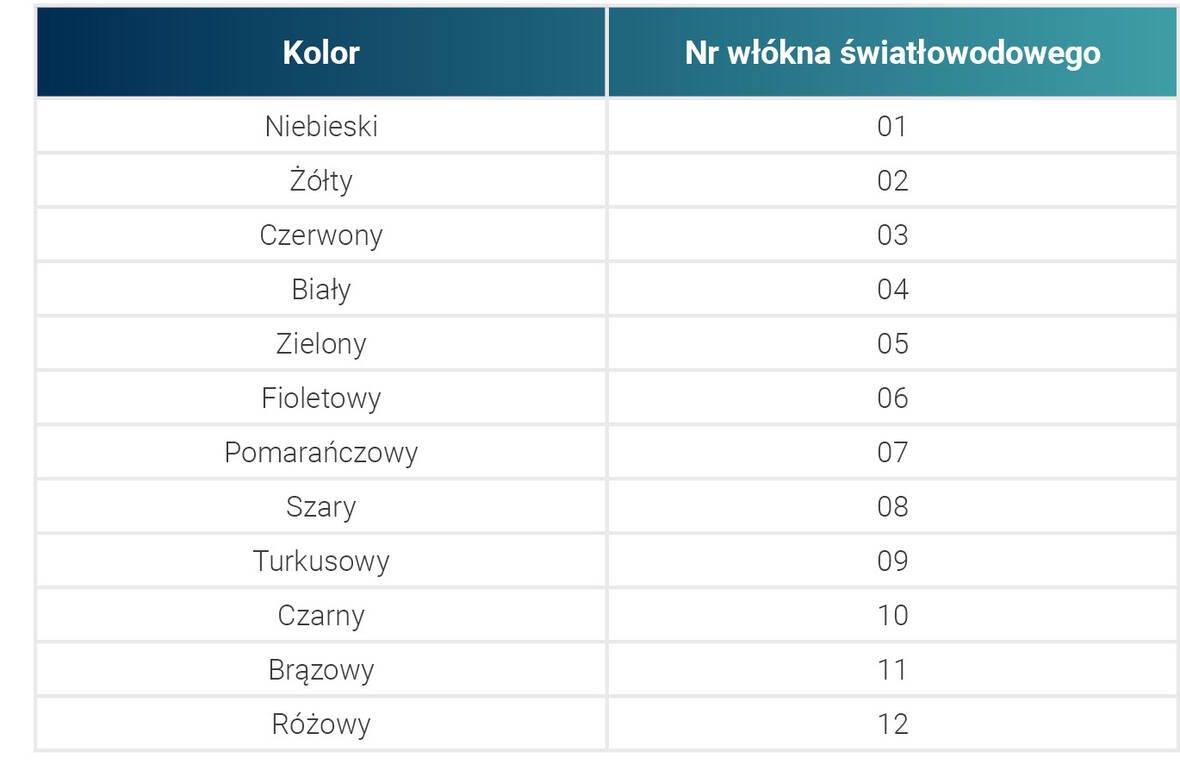
Table 1: Selection of fiber optic color codes according to EN 60794-2
Interested in our special offer
for fiber optic networks?
Contact me:
Krzysztof Bicki | tel. 500244864 | bicki@assmann.pl
Fiber optic cable - construction
-
The final optical fiber cable consists of a specific number of optical fibers enclosed within a tube, which is located inside the cable. Consequently, we can distinguish between cables with a single-tube construction or multi-tube construction. However, the most popular multiples of optical fibers commonly found in the market in optical cables are 2, 4, 8, 12 (further numbers are multiples of 12).
When designating the number of optical fibers in single-mode cables, the notation typically looks like: 2J, 4J, 8J, 12J, 24J and so on. For multimode cables, the notation appears as:: 4G, 8G, 12G, and so forth.
To reinforce the overall cable structure, tubes are often surrounded by aramid fibers or fiberglass, and there is often a strengthening element placed in the central part of the cable. Some cables also use steel tape for structural reinforcement.
One of the key parameters of optical fiber cables unrelated to transmission is a mechanical parameter describing the maximum allowable tensile strength of the optical fiber cable during its installation in cable ducts or channels. For optical fiber cables used in LAN networks, this parameter should be a minimum of 1500N. When laying the cable with the appropriate tensile force, it's also important to consider the manufacturer's allowable minimum bending radii for the cable. Typically, two parameters are provided: the minimum allowable bending radius during installation of the cabling and the minimum bending radius for the cable once it's already installed.
-
The finishing touch of the optical fiber cable is, of course, the outer jacket. The most commonly encountered outer jacket materials for optical fiber cables on the market are polyethylene (PE) and a jacket with ow smoke zero halogen (LSOH) properties. The LSOH jacket is made from halogen-free materials, does not support flames, and emits minimal smoke when exposed to fire.
There is also a standardized color-coding system for the outer jackets of optical fiber cables. Cables designed for outdoor use typically come in black, while for indoor cables, it appears as follows:
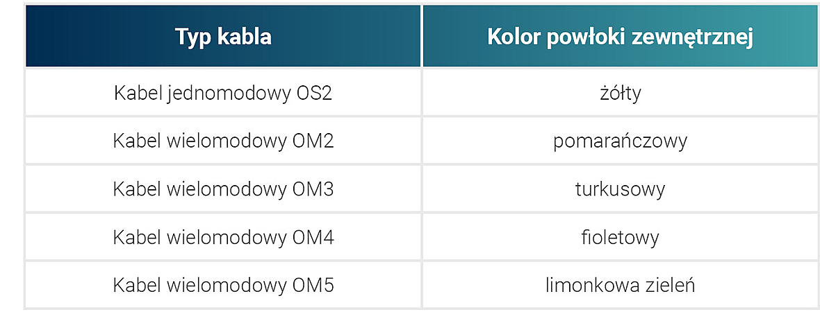
Table 2: Applied color scheme of inner cable sheaths.
Attenuation, Waves, and Connectors
-
When building fiber optic connections, it's important to remember that optical fiber is not a lossless medium. The optical signal traveling through the optical fiber experiences attenuation, which increases with the length of the transmission path. The table below presents the maximum allowable attenuation specified by the particular optical fiber, depending on the wavelength of the optical signal. It's worth noting that transmission at wavelengths of 850 and 1300 nm is reserved for multimode fibers, while single-mode fibers typically use wavelengths of 1310 and 1550 nm.
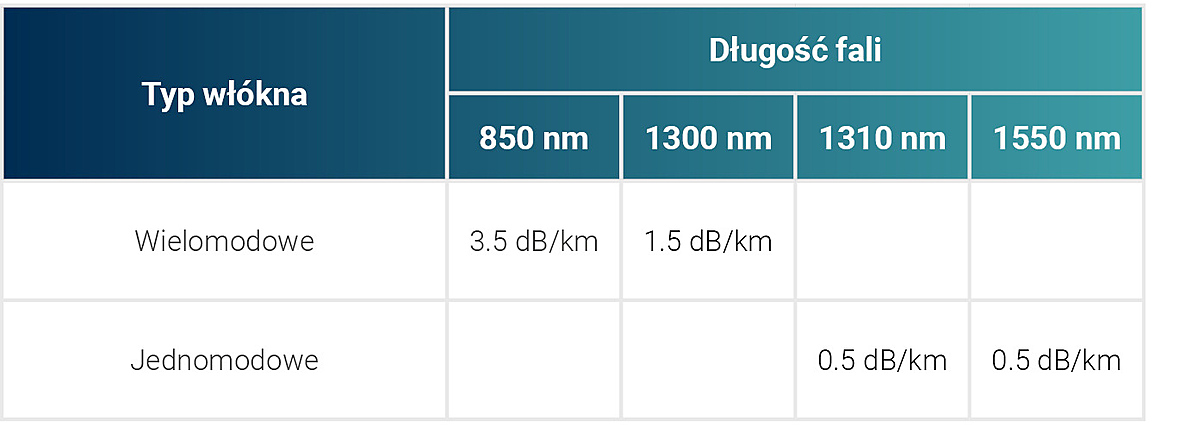
Table 3: Maximum Allowable Attenuation for Specific Optical Fiber Depending on the Wavelength of the Optical Signal
An interesting fact about decibels ([dB]) and the logarithmic scale is that a 3 dB attenuation corresponds to a situation where only half of the power of the signal transmitted by the transmitter reaches the receiver in the optical fiber. For instance, a 10 dB attenuation means that only 10% of the input signal's value remains at the output of the optical path.
To enable data transmission in an optical fiber link, in addition to the mentioned cable, the use of additional connecting elements is required, such as pigtails and patch cords.
-
The connection between cables and pigtails, which are typically placed in fiber optic switches/junction boxes, is achieved through fusion splicing. Each splice or connector in a connection, such as a patchcord/pigtail, introduces additional attenuation in the transmission path. The maximum allowable value of such attenuation is specified in the table below:

Table 4: Maximum Allowable Attenuation in the Transmission Path
For fiber optic connections, there is a specific group of connectors designated. Just as in copper-based telecommunications, the RJ-45 connector is the standard connector; in fiber optic connections, you commonly use connectors such as LC, SC and E-2000. In industrial environments where challenging conditions like movement, vibrations, and stress are present, threaded connectors like ST and FC are employed.
In the case of single-mode accessories, connecting elements like pigtails and patch cords can have two different types of connectors: PC (blue color) and APC (green color). The difference between these connectors lies in how the end face of the optical fiber is terminated in the connector. APC connectors must provide a minimum return loss of 60 dB (higher values are better - we aim to minimize reflected signals that re-enter the transmission path), while PC connectors ensure a minimum return loss of at least 35 dB.
Capacity of fiber optic cable
-
The data transmission speed in fiber optic networks, measured in Mb/s (megabits per second) or Gb/s (gigabits per second), that can be offered to end-users is, in a sense, unlimited. The maximum speed limit is constantly being pushed higher due to the development of laser technologies and the implementation of increasingly advanced data multiplexing systems in transceiver devices.
Multimode fiber optic is best suited for applications within buildings, and the length of the fiber link used will determine the maximum data transmission speed that can be achieved. For example, the length of the link:
- Up to 2000 meters is suitable for data transmission speeds of 155 Mb/s or lower
- Up to 550 meters is suitable for data transmission speeds of 1 Gb/s or lower
- Up to 300-400 meters is suitable for data transmission speeds of 10 Gb/s or lower
- Up to 150 meters is suitable for data transmission speeds of 100 Gb/s or lower.
-
Single-mode optical fiber is best suited for situations where:
- The required throughput exceeds the capabilities of multimode fiber.
- The length of the link exceeds the capabilities of multimode fiber.
- A specific application demands the use of single-mode fiber.
Detailed information about fiber optic link lengths and the types of applications that can be supported at these lengths is provided in the two tables below:
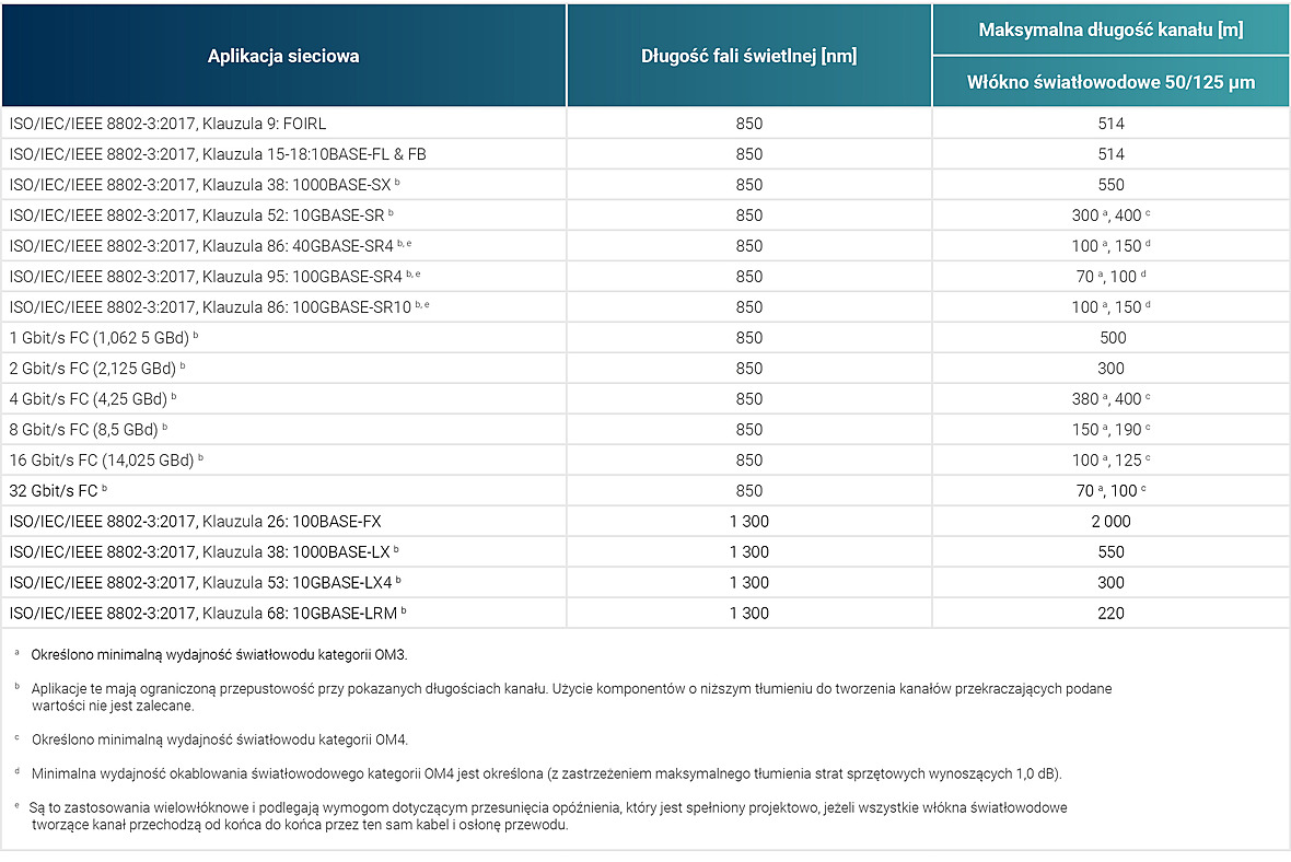
Table 5: Maximum Lengths of LAN Channels Supported by Fiber Optic Applications for Multimode Connections
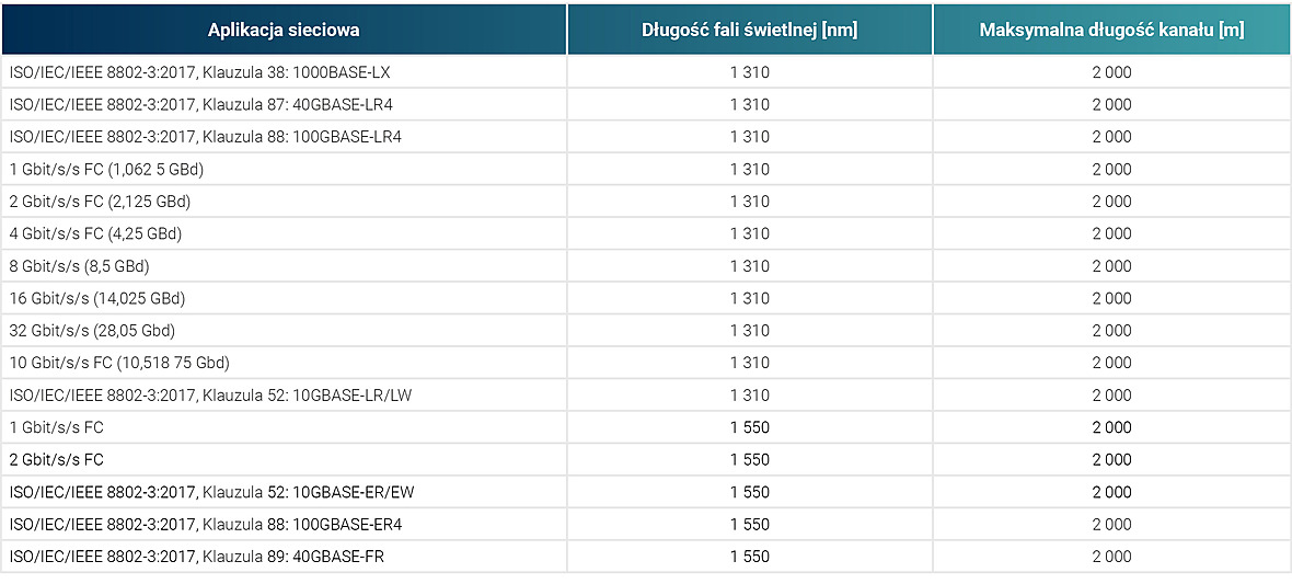
Table 6: Maximum Lengths of LAN Channels Supported by Fiber Optic Applications for Single-Mode Connections
Copper Wiring or Fiber Optic? Single-Mode or Multimode Fiber?
-
The question often arises: Which transmission medium should be used - copper cabling or fiber optic cable? What type of fiber optic cable should be chosen? Of course, there is no one-size-fits-all answer to these questions because the choice of the appropriate technology depends on several factors. Specifically:
- Distance. For short distances up to 100 meters, copper cabling is typically the preferred choice. For links not exceeding 2 kilometers, multimode fiber cables are commonly used, while single-mode fiber cables are suitable for connections longer than 2 kilometers.
- Cost. In scenarios where there are many cross-connections between a fiber optic network and a copper network, and where multiple active devices equipped with transceiver modules like GBIC, SFP, SFP+, or QSFP are required, it is essential to conduct cost calculations to determine which transmission medium is more cost-effective. In such cases, you must find the answer to whether you will implement fiber optic medium based on single-mode cabling or multimode cabling.
- Distance. For short distances up to 100 meters, copper cabling is typically the preferred choice. For links not exceeding 2 kilometers, multimode fiber cables are commonly used, while single-mode fiber cables are suitable for connections longer than 2 kilometers.
-
- Other guidelines/restrictions. In this context, various other factors can be listed that determine the use of a specific data transmission technology. For example, the requirement for the medium to remain compliant with the telecommunications operator's external medium, the need for electromagnetic interference resistance, the requirement for a minimum data transmission speed, and so on..
In practice, the construction of the physical layer of a LAN network within a facility often involves laying fiber optic cables as building backbone cables, connecting building distribution points to floor distribution points. Meanwhile, copper cabling is used for connections between floor distribution points and telecommunication outlets/logical electrical points. Transitioning from one transmission medium to another is accomplished through the use of dedicated devices (media converters, network switches) at distribution points. This type of solution, where two types of cabling are connected, allows for achieving high data transmission speeds, such as 10 Gb/s, while simultaneously saving costs.
Fiber optic technology provides high capacity, stability, and data transmission range - no other transmission medium allows for the simultaneous achievement of all these parameters in a transmission link.
The advantages of fiber optic cables in a nutshell
-

Reliable and high-speed data transmission (up to hundreds of Gb/s)

No interference from external electromagnetic fields

No risk of damage or fire due to short circuits, etc.

Easy installation in telecommunications ducts

Lower susceptibility to theft compared to copper wiring - due to the absence of "desirable" precious metals in the cable construction.
-

Long transmission range of up to several hundred kilometers

Lack of mutual interference

No need for surge protection measures

Lighter weight compared to copper cables
-

Wide operating bandwidth - THz (Terahertz).

Inability to eavesdrop on transmissions

No need for shielding connections

The possibility of blowing into cable ducts
Hungry for knowledge? Download our brochure
Basic knowledge of cooper and fiber optics


